TB STRUCTURES
TimbyrNode
TimbyrNode reduces mass timber truss or frame design time from weeks to days and from days to hours. It designs dowelled and bolted mass timber connections to Eurocode 5, driven either by IDEA StatiCa Connection CBFEM forces or by your own input, and within a minute guides you to a manufacture-ready physical connection in Tekla Structures. Precision is achieved with an omnidirectional auto-alignment algorithm that adjusts the plate polygons and fasteners. The inevitable slight differences between the physical and analytical models are automatically corrected. The detailer's effort is only a few clicks. STEP export included.
1. Scope
TimbyrNode designs steel-to-timber dowelled and bolted connections two ways: by reading a connection from IDEA StatiCa Connection (.ideacon), or by building one from scratch directly in TimbyrNode (Manual Input).
-
From IDEA StatiCa - members, fastener layout, timber and steel materials, and per-shear-plane bolt forces come directly from a CBFEM model.
-
From scratch (Manual Input) - you enter the members, loads, steel plate and fastener grids, and TimbyrNode derives the per-shear-plane bolt forces itself.
Either way, the session saves to a plain-text .tce file you can reopen in TimbyrNode at any time.
Connection topologies covered:
-
External plates - timber member sandwiched between two outer steel side plates (2 shear planes)
-
Internal plates - 1/2/3 steel plates slotted into the timber member (2/4/6 shear planes)
In-plane (2D) planar truss and frame connections are fully verified. Out-of-plane (3D) members imported from IDEA StatiCa are now checked in their own fastener plane at any framing angle (spacing, effective fastener count, splitting, block and plug shear, steel-plate bearing); this out-of-plane analysis is new and should be reviewed. Building from scratch is for in-plane (XZ) connections.
Importing a connection uses your IDEA StatiCa v25.1 or later Steel licence and its CBFEM solver. Manual Input is the path for when you are not starting from an IDEA StatiCa model, and runs directly in TimbyrNode.
2. Manual input
Build and check a connection directly in TimbyrNode.
-
Enter members, member forces, the steel plate and the fastener grids; the connection is calculated and drawn live.
-
External and 1/2/3 inserted-plate topologies, the same set as the IDEA StatiCa path.
-
Multiple load cases on one connection, calculated one at a time.
-
Continuous members carry a force on each side (Begin and End). A live equilibrium readout shows the force balance at the node, the same check as IDEA StatiCa's Unbalanced forces panel.
-
Node-end cuts (square, mitre, priority, edge), staggered fastener grids (EN 1995-1-1 Figure 8.7), and individual fasteners switched on or off.
-
Undo and Redo throughout.
-
Or continue an IDEA StatiCa connection: open an extracted connection in the editor, keep editing it, and switch at any time between the original IDEA StatiCa answer and your edited design, with a drift readout of how far the design has moved.
Connections built from scratch export to Tekla Structures and STEP, and produce the PDF report, exactly like a connection extracted from IDEA StatiCa.
3. Eurocode 5 (EN 1995-1-1) checks
Full EN 1995-1-1:2004 check stack for steel-to-timber bolted and dowelled connections:
-
Johansen failure modes per fastener (double-shear steel-to-timber modes f-h and j-m)
-
Group check with effective fastener number n_ef (Sec 8.2.4)
-
Perpendicular splitting (Sec 8.1.4)
-
Block and plug shear (Annex A)
-
Multi-plate, multi-shear-plane support: 1-plate (2 shear planes), 2-plate (4 shear planes), 3-plate (6 shear planes)
-
Edge distance and spacing checks (Tables 8.4 and 8.5)
-
Steel plate and steel-side fastener capacity to EN 1993-1-8:2005, included in the pass/fail verdict
-
Fire design per EN 1995-1-2, classes R15 to R60, with charring of the timber section and optional protection (gypsum-F board, head cover, glued-in strip). Fire results are preliminary and should be independently verified by the responsible engineer.
For every shear plane TimbyrNode computes a Johansen resistance using the correct timber thickness for that plane. When the failure modes are kinematically compatible across all planes (Sec 8.1.3(2)), the per-plane resistances are summed and the total is checked against total demand. When the modes are not compatible, TimbyrNode falls back to the governing per-plane utilisation.
4. Validated worked examples
TimbyrNode ships with worked examples, including published textbook and benchmark cases that the engine reproduces:
-
COST FP1402 splice connection
-
Porteous and Kermani apex and moment connections
-
The Frangi fire example
-
Truss nodes
Each opens as a fully editable session and reproduces the reference capacities and fastener forces of its source, so you can see the engine checked against the literature and use the examples as starting points.
5. Session files (.tce)
Every session saves to a plain-text .tce file. No proprietary format, no encryption. Anyone with TimbyrNode can open one. The file carries the full connection, including a from-scratch model, its load cases and the chosen report language.
Why it matters:
-
Email a connection to a colleague, checker or client for review - they only need TimbyrNode to open it
-
Open the file in any text editor to audit inputs or compare revisions
-
Files stay readable years later without needing the original software
-
Reopen any saved session to continue the check where you left off
6. PDF output
A single PDF report ready for building-authority submission, in English or German.
-
Per-fastener EC5 derivation, typeset with proper engineering notation
-
Group check math: n_ef, splitting, block and plug shear
-
Per-plane Johansen mode summary, with an explicit failure-mode compatibility statement per Sec 8.1.3(2)
-
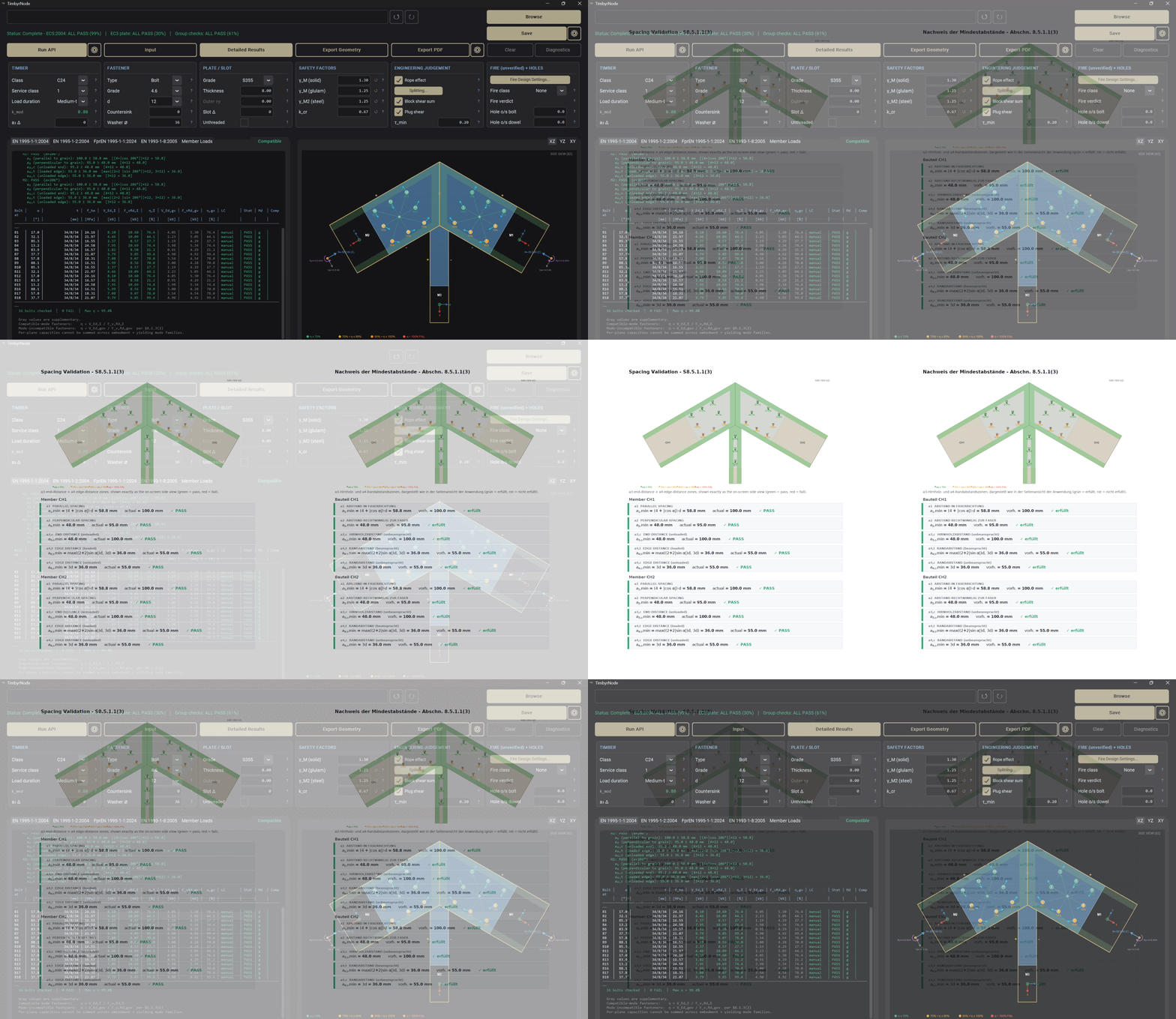
Edge and spacing check results, with a side view of the end and edge distance zones
-
Steel plate check to EN 1993-1-8
-
Fire design result
-
Member force vectors on the side view, and per-fastener shear vectors for connections built in TimbyrNode
-
Embodied carbon and steel weight
The German report uses the normative DIN EN 1995-1-1 terminology throughout. For a 3D connection the report adds the out-of-plane views.
7. STEP output
3D geometry as STEP AP214 (ISO 10303-21).
-
Analytical B-Rep, not tessellated
-
Plates as extruded polygons with CIRCLE holes
-
Bolts and dowels as analytical CYLINDRICAL_SURFACE
8. Tekla Structures output
Pushes the connection straight into Tekla Structures.
-
Automatic plate-edge and fastener alignment
-
Recesses and dowel holes as boolean cuts
-
Bolts as native bolt group elements
-
Works with Tekla Structures 2022 and later
-
Works with multiple Tekla instances running at the same time - you choose the export target version
9. Compatibility of failure modes and CBFEM
Eurocode 5 Sec 8.1.3(2) permits summing per-plane resistances only when the failure modes are kinematically compatible across all shear planes. Whether that compatibility holds depends on the force each plane actually carries, which is not equal across planes.
TimbyrNode reads the per-plane bolt forces directly from CBFEM and runs Johansen plane-by-plane via topology dispatch per Sec 8.1.3(1), using the correct timber thickness for each plane. TimbyrNode sums the resistances and checks the total against total CBFEM demand. When compatibility of failure modes is not achieved, summation would overstate capacity. In this case TimbyrNode falls back to the worst per-plane utilisation.
Classical hand-calculation assumes all planes carry equal force and always sums. That works in fully ductile regimes. It is unconservative in non-ductile ones: thin timber, thick fasteners, brittle mode governing. TimbyrNode is the only tool known to consume IDEA StatiCa's per-plane CBFEM forces and apply Johansen plane-by-plane against each one.
When you build a connection from scratch, TimbyrNode derives the per-plane forces itself from a rigid-elastic distribution with strip equilibrium across the shear planes, then applies the same plane-by-plane Johansen check.
10. Verification
Verification 1 - P&K Example 12.8.1 - External moment connection, two outer steel side plates
-
Plate configuration: External, 2 plates, 2 shear planes, 12 mm plates
-
Timber: C24, cross-section 72 x 294 mm (12 + 72 + 12 with steel plates)
-
Fasteners: M12, grade 4.6
-
Loading: Rotational
-
Special checks: None
Verification 2 - P&K Example 12.8.3 - Apex connection, one inserted steel plate
-
Plate configuration: Internal, 1 plate, 2 shear planes, 8 mm plate
-
Timber: C24, cross-section 75 x 300 mm (33.5 + 8 + 33.5 with steel plate)
-
Fasteners: M12, grade 4.6
-
Loading: Rotational (with axial)
-
Special checks: Rope effect
Verification 3 - COST FP1402 §4.3 - Internal multi-plate joint, 8 bolts, axial loading
-
Plate configuration: Internal, 2 plates, 4 shear planes, 10 mm plates
-
Timber: GL24h, cross-section 300 x 160 mm (95 + 10 + 90 + 10 + 95 with steel plates)
-
Fasteners: M16, grade 4.6
-
Loading: Translational
-
Special checks: Rope effect, block shear